Automated 3D measurements of magnetic fields
We are able to measure and visualize precise magnetic fields of an object in three dimensions.
Magnetic measurement of the bell of a brushless motor
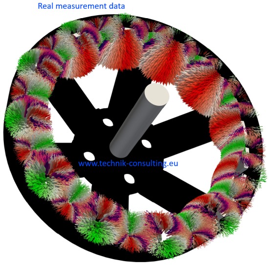
Foto: Dirk Brunner; Lizenz: CC BY SA 3.0
The measurements shown here are hybrids. Real measurement data was combined with CAD models. This makes the assignment easier. In addition, the vectors have been appropriately colored so that the north pole and south pole can be clearly seen, even if the individual magnets within the bell are rotated, the poles are displayed correctly. This representation is unique and enables any errors and optimization opportunities to be identified quickly.
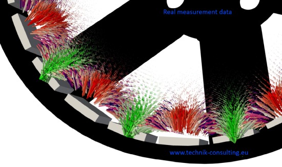
Foto: Dirk Brunner; Lizenz: CC BY SA 3.0
Automated measurement of the Halbach array
If you want to know how good your Halbach array is and how the magnetic field is distributed in space, you have come to the right place. We scan precise three-dimensional magnetic fields in space and visualize them.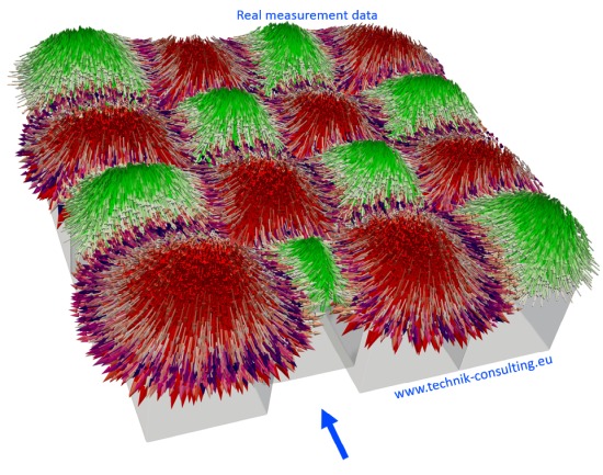
Foto: Dirk Brunner; Lizenz: CC BY SA 3.0
The three-dimensional representation allows any two-dimensional cutting planes to be created and the magnetic field strength in this area to be examined. When developing a two-dimensional linear motor, important statements can be made in advance. Optimization is much easier.
Bilddatei "" in der Kategorie "" nicht vorhanden
Foto: Dirk Brunner; Lizenz: CC BY SA 3.0
Foto: Dirk Brunner; Lizenz: CC BY SA 3.0
The measured 3D data can be further processed depending on requirements. Here you can see a section through the Halbach array. The course of the magnetic field strengths can be clearly seen.
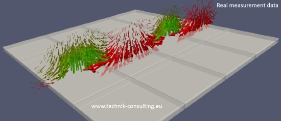
Foto: Dirk Brunner; Lizenz: CC BY SA 3.0
Schnittdarstellungen sind an beliebigen Positionen und in beliebigen Schnittebenen möglich.
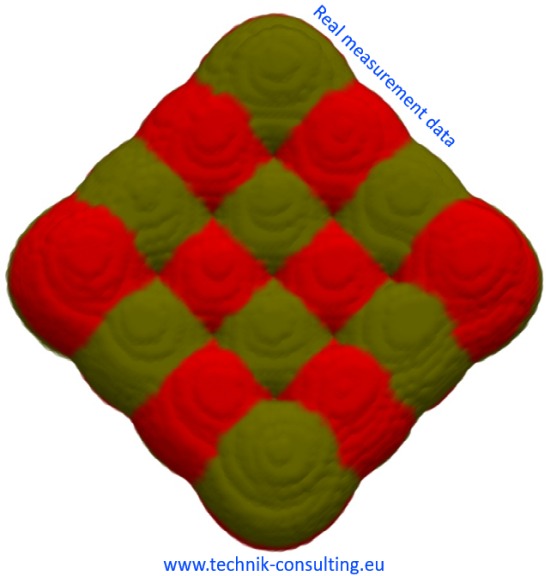
Foto: Dirk Brunner; Lizenz: CC BY SA 3.0
Course of the magnetic field strengths of a Halbach array from a bird's eye view. The North Pole and South Pole are color coded in red and green respectively. The smaller magnetic areas in the center (4 magnets) can be clearly seen, compared to the magnetic fields in the edge area (12 magnets). The corner magnets are particularly pronounced in terms of the size of the magnetic field because the opposite pole is missing.
Long-term measurement of magnetic fields
Do you suspect that magnetic fields have caused changes in your manufacturing process or quality assurance?For example, a nearby railway line can generate a magnetic interference field due to a passing train. This magnetic interference field can in turn influence your measurements. A long-term measurement of the magnetic field on site can provide information here.
The high-precision long-term measurement can even detect changes in the earth's magnetic field. Did you know that the Earth's magnetic field fluctuates by a certain value every day? Depending on where the sun is.
This can also be determined in three dimensions using the high-precision long-term measurement of the magnetic fields. If desired, in several locations at the same time.
Automated 3D measurements of magnetic fields are particularly suitable for the following areas:
- quality assurance
- forensic science
- Research and science
- Electric motor construction
- Checking simulation results of a magnetic field simulation
- Sample measurement
- Measurement of residual magnetization
- Automated magnetic field measurements
- Measuring magnetic fields on circuit boards and conductor tracks
- Automated 3D measurement of magnetic fields
Typical magnetic field strengths in the area
| Description | Tesla or "T" | Millitesla or "mT" | Mikrotesla or "μT" | Gauß or "G" |
|---|---|---|---|---|
| Earth's magnetic field in Germany | 0,00005 | 0,05 | 50 | 0,5 |
| Limit value for electromagnetic fields in devices | 0,000 1 | 0,1 | 100 | 1 |
| Weak refrigerator magnet (e.g. made of foil) | 0,02 | 20 | 20000 | 200 |
| Fridge magnet strong | 0,1 | 100 | 100000 | 1000 |
| Air gap speaker magnet (small, inexpensive) | 0,2 | 200 | 200000 | 2000 |
| Strong (NdFeB) magnet on one pole | 0,5 | 500 | 500000 | 5000 |
| Between two strong (NdFeB) magnets at the poles | 1,2 | 1200 | 1200000 | 12000 |
| Magnetic resonance imaging “nuclear spin” | 2 | 2000 | 2000000 | 20000 |
Our measurements are a fully automatic and high-precision measurement of magnetic fields with a minimum spatial resolution of 0.1 mm and a magnetic field resolution of up to 20 nT. Note: The very weak earth's magnetic field is approx. 2000 times stronger.
Depending on the measurement object, a suitable measuring head is selected and the sensitivity of the magnetic measuring head is adjusted. This achieves optimal resolution when measuring the magnetic field.
The measuring machine was specially developed and is in constant development.
The measuring points are calculated in advance using special software and then actually measured using a specially developed measuring head. The measuring head can precisely measure bores with an inner diameter of at least 6 mm. Smaller measuring heads or drilling diameters on request.
Depending on the application, automated measurements can be carried out with any geometry and resolution. The automated measurement process and special algorithms mean that there is no need for complex shielding. A special shielding chamber is not necessary.
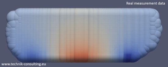
Foto: Dirk Brunner; Lizenz: CC BY SA 3.0
Measurement 1: Measurement of magnetic field + interference field --> this measurement is usually sufficient
Measurement 2: Measurement without sample. Only the interference field (e.g. earth's magnetic field, magnetic field of a switched off loudspeaker) is measured at exactly the same location coordinates.
Data processing: Measurement 1 – Measurement 2 = magnetic field of the sample without interference signal
Automated measurement has many advantages over freehand measurement. The automated three-dimensional measurement of the magnetic field strength produces reproducible measurement results.
The automated magnetic field measurements are vector measurements, which means that the strength and direction of the magnetic field is known at every measuring point in space. Common handheld measuring devices only show the strength of the magnetic field, but not the direction.
Compare a vector measurement of the magnetic field versus a pure measurement of the magnetic field strength.
Foto: Dirk Brunner; Lizenz: CC BY SA 3.0
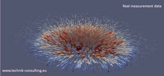
Foto: Dirk Brunner; Lizenz: CC BY SA 3.0
The vector data of the magnetic field can be easily represented in three dimensions. This allows a deeper understanding of the course of the magnetic field lines and the resulting magnetic forces to be gained. Optimizations, troubleshooting and quality controls are easier.
New insights can be gained through the use of state-of-the-art, high-precision sensor technology in conjunction with powerful data processing and algorithms. Magnetic fields that are otherwise impossible to detect or are very difficult to detect can be visualized.
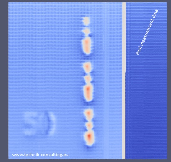
Foto: Dirk Brunner; Lizenz: CC BY SA 3.0
A typical example is forensics. Even the smallest magnetic fields can be recorded and assigned here, such as:
- Counterfeit coins/counterfeit money
- Knife (assignment to a production batch or a magnetic knife holder)
- Deliberate deletion of magnetic strips (e.g. credit card) using a permanent magnet. Depending on the starting bearing, the magnet and the direction of movement of the magnet can be determined here.
- Evidence of magnetic manipulation of devices.
- Magnetic screwdriver in combination with a screw. Even with (almost non-magnetic) stainless steel, residual traces can be detected and possibly assigned to a tool.
- Detection of magnetic traces on metal parts and their graphical representation.
IMPORTANT: Please contact us before handling the objects to be examined. Weak magnetic fields are quickly destroyed or altered through improper handling.
Custom measurements of three-dimensional magnetic fields
The following data is shown with the kind permission of our customers.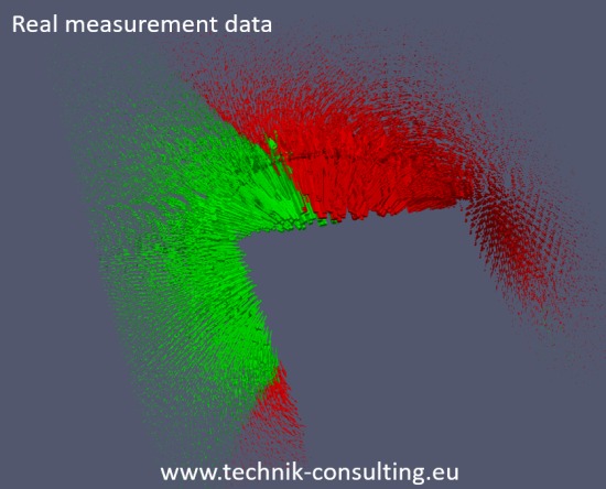
Foto: Dirk Brunner; Lizenz: CC BY SA 3.0
Measurement and visualization of a customer-specific component. The cut and color of the measured magnetic fields in the room were adjusted according to customer requirements. The visible vectors of the magnetic field correspond to just 1% of the measurement data. The component itself is only a few mm large.
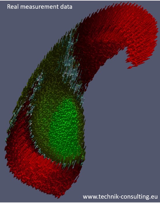
Foto: Dirk Brunner; Lizenz: CC BY SA 3.0
Visualization of residual magnetic fields on a component through the production process. By highlighting the field boundaries in white, it is much easier to determine which production process creates this magnetic field. On the one hand, the residual magnetic field can simply be eliminated and, on the other hand, from a forensic perspective, the object can be clearly assigned to a company. This goes so far that the object can be assigned exactly to a machine and a tool.
Magnetic 3D measurement of a permanent magnet made of AlNiCo
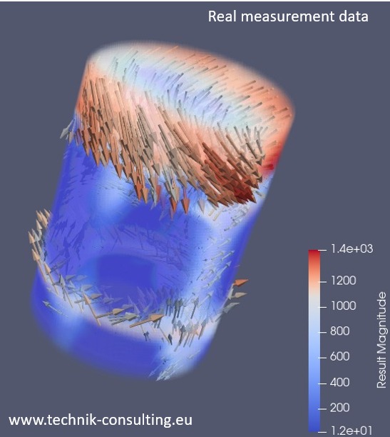
Foto: Dirk Brunner; Lizenz: CC BY SA 3.0
The sample diameter is 3.0 mm. The magnetic field was specially shaped and can be seen particularly well in vector space. The vector arrows point from the North Pole to the South Pole.
Magnetic measurement of brushless motors
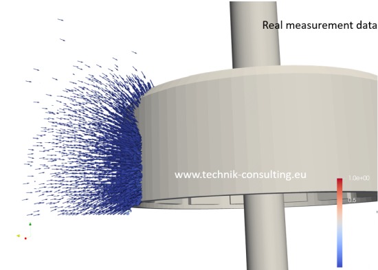
Foto: Dirk Brunner; Lizenz: CC BY SA 3.0
Magnetic field outside the bell of a brushless motor (BLDC). For better representation in a slice image of the measured magnetic field.
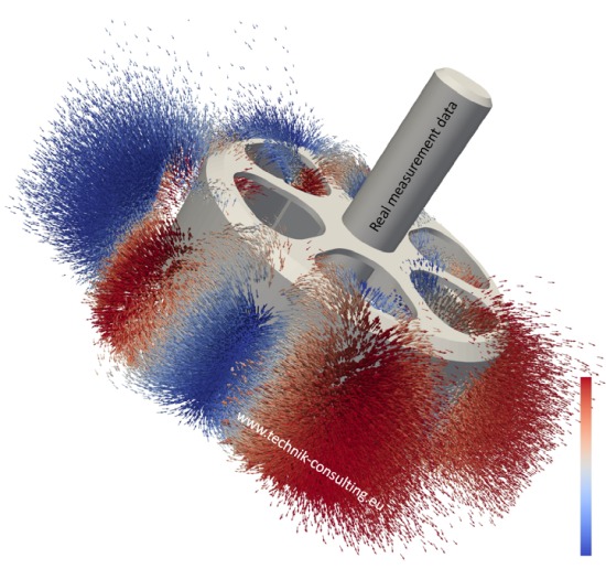
Foto: Dirk Brunner; Lizenz: CC BY SA 3.0
Here the magnetic field of a BLDC motor outside the bell was measured and displayed. The magnetic flux can be easily recognized using special algorithms. The coloring was carried out according to customer requirements.
Typical magnetic field measurements provide little or no information about the expected magnetic forces within the motor. Using mathematical/physical models, the real measurement data can be transformed or converted in such a way that the expected magnetic forces can be determined.
Magnetic field stator of a BLDC motor
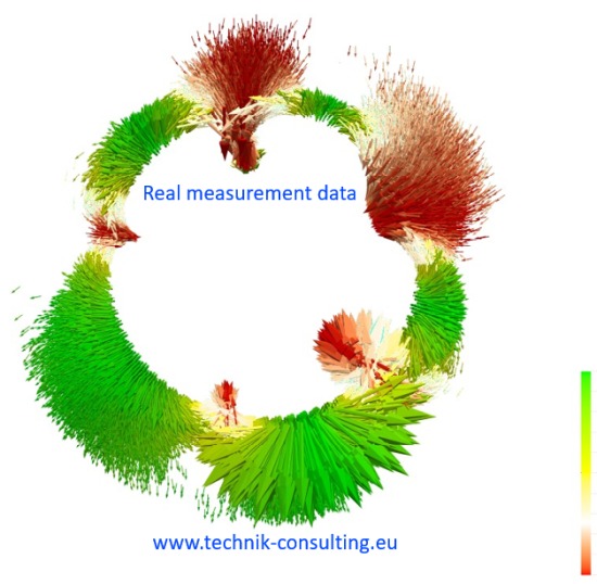
Foto: Dirk Brunner; Lizenz: CC BY SA 3.0
Measuring the magnetic field of a stator from a BLDC motor. The coils were loaded with a defined current. The distribution of the magnetic field can be viewed in real terms, including the manufacturing tolerances. Here too, the vectors were specially colored. This enables better allocation to the bell and the forces associated with it.
The measurement data can be ideally used to optimize the simulation model and to know the real magnetic field strengths. In addition, the orientation of the magnetic field in space can be perfectly recognized.

Foto: Dirk Brunner; Lizenz: CC BY SA 3.0
Using advanced data analysis or algorithms, the winding pattern of the brushless motor can be determined based on the measurement data. Even a completely cast stator can be analyzed magnetically in more detail.
Lots of room for optimization!
Magnetic measurement of a magnetic film
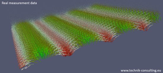
Foto: Dirk Brunner; Lizenz: CC BY SA 3.0
Here, a holding magnet in the form of a film was measured and the data was visualized. The pole spacing of the strip poles is 4 mm. Through the automated three-dimensional measurement of the magnetic fields, the production process can be controlled in terms of quality. The smallest errors and irregularities can be displayed, which means that a magnetic fingerprint can be created on the magnetic foil. This means that, from a forensic perspective, an assignment can be made.
Residual magnetic field on a stainless knife
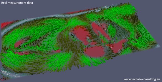
Foto: Dirk Brunner; Lizenz: CC BY SA 3.0
The residual magnetic field of a stainless knife is shown here. The magnetic field was created by a magnetic knife holder. In this case, the magnetic knife holder was self-made, which meant that the magnets had an individual arrangement. Due to the residual magnetic field in the knife, it can (almost) undoubtedly be assigned to this knife holder. From a forensic perspective, a stroke of luck.
Really measure magnetic field holding magnet
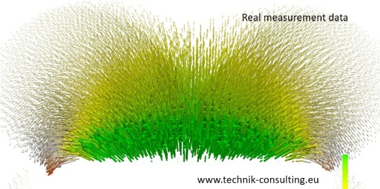
Foto: Dirk Brunner; Lizenz: CC BY SA 3.0
Here the magnetic field of a holding magnet can be seen in cross section.
Magnetic field of a twisted cable
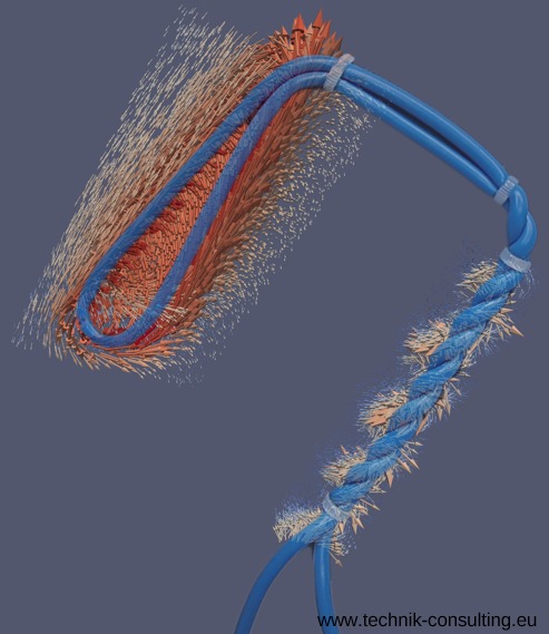
Foto: Dominik Brunner; Lizenz: CC BY SA 3.0
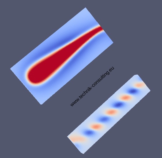
Foto: Dominik Brunner; Lizenz: CC BY SA 3.0
Here you can see the magnetic field of a twisted and untwisted cable in comparison. With the twisted cable, the magnetic fields are partially canceled out, which is why they are significantly weaker. With the non-twisted cable, this acts like an elongated coil. The magnetic fields add up.
If the magnetic field of a live cable is to be small, the forward and return cables should be twisted together. This greatly weakens the magnetic interference field.
Contact us if you want to measure magnetic fields precisely and three-dimensionally.